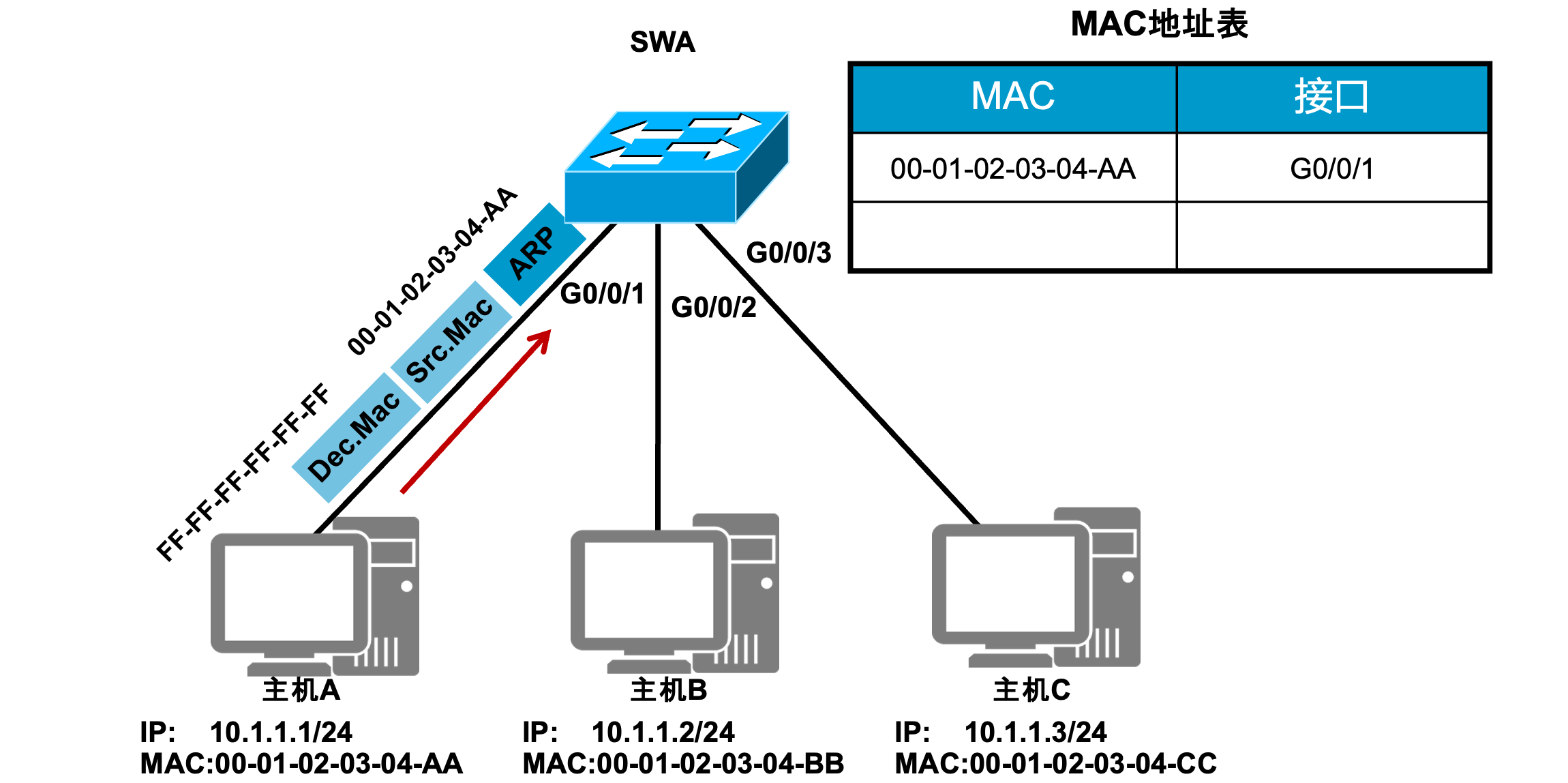
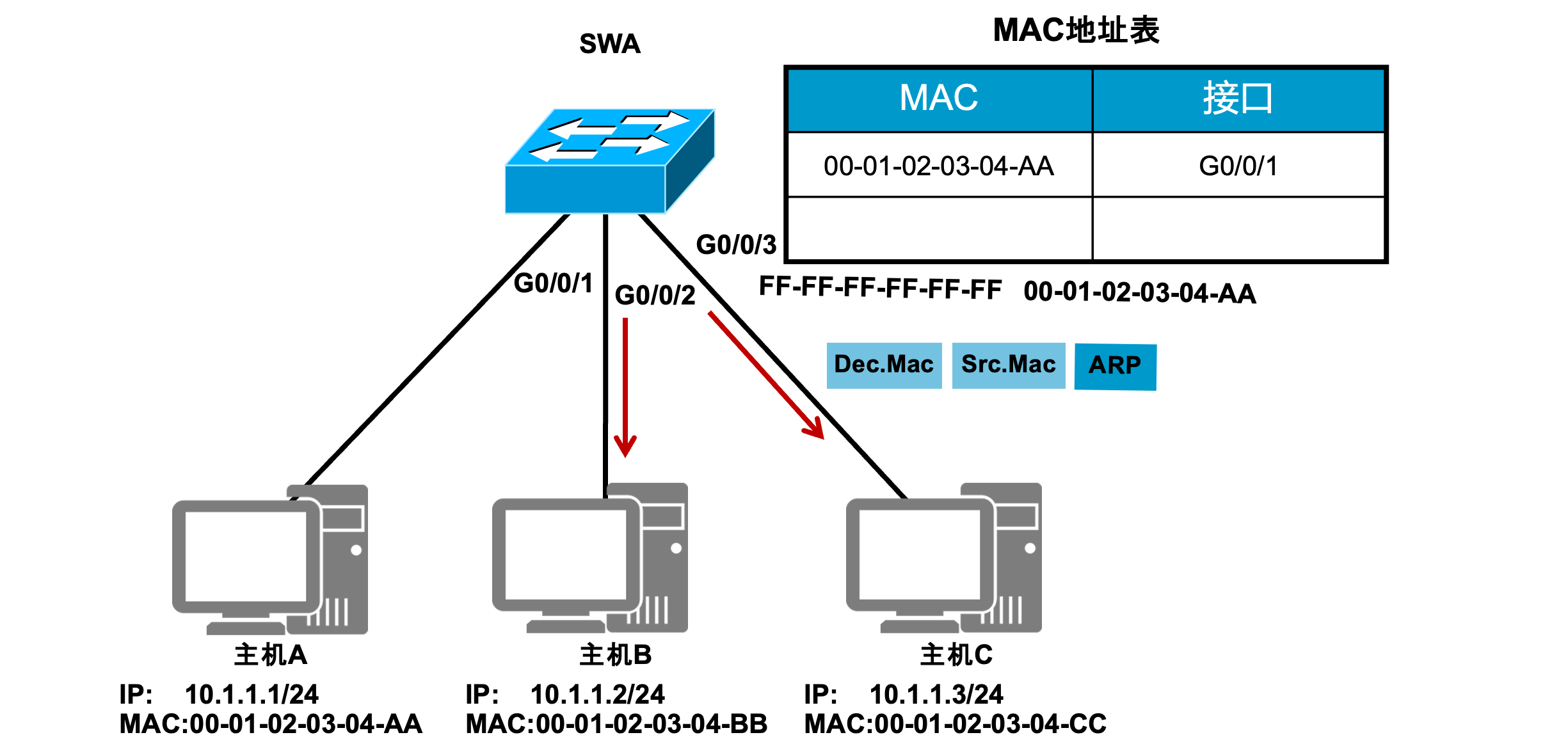
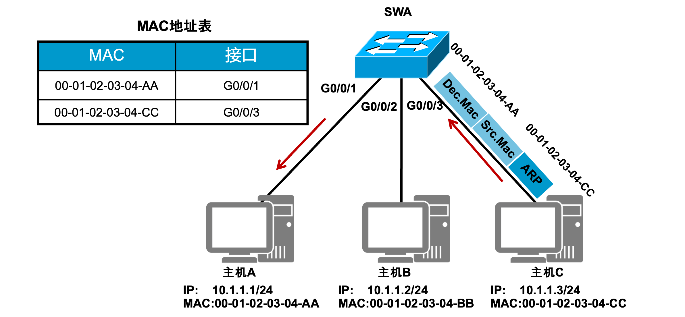
交换机根据 MAC地址 表将目标主机的回复信息单播转发给源主机(主机A),并将发送方主机C的 MAC 地址和对应接口信息记录在交换机的 MAC地址表 中。
VLAN 技术
引言
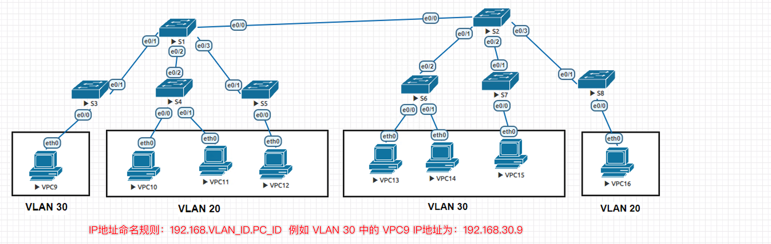
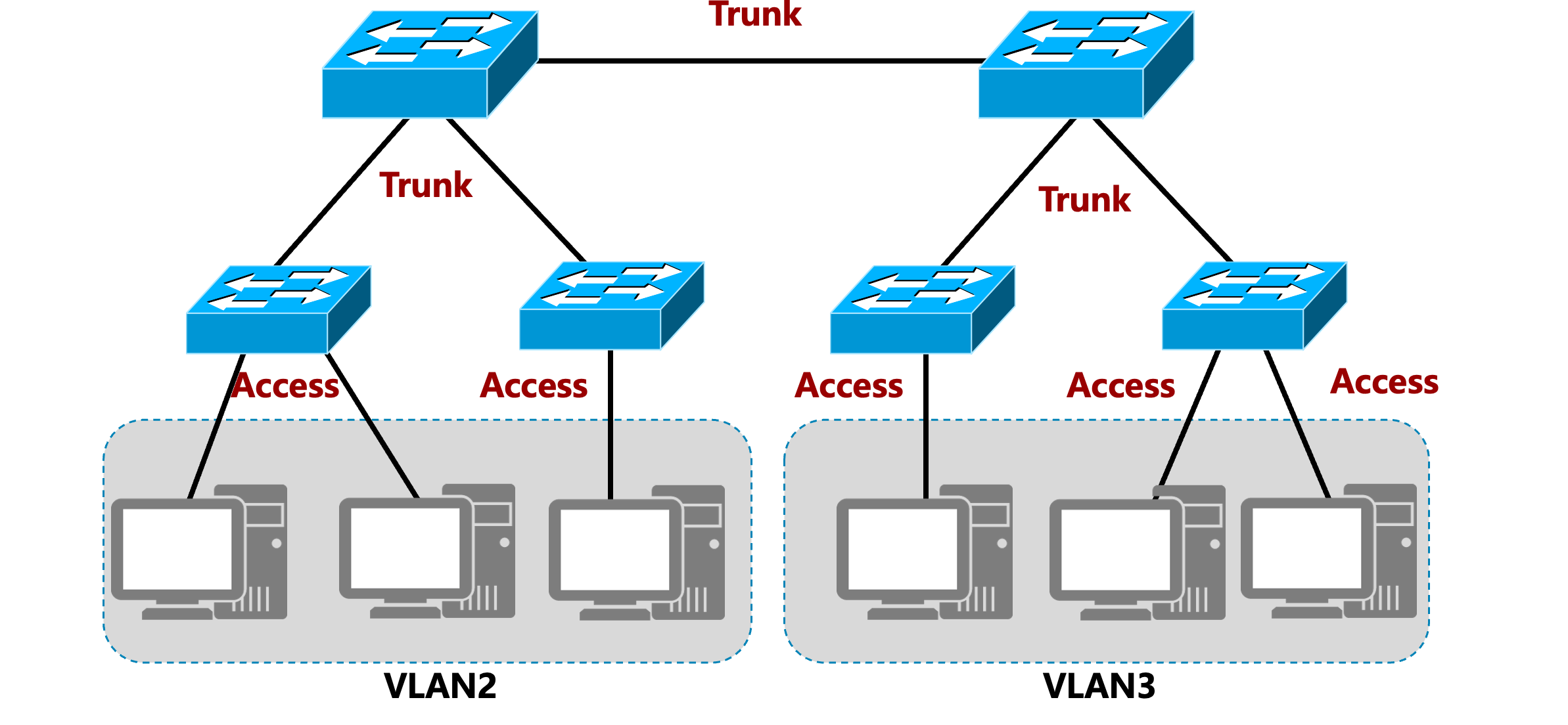
随着网络中计算机的数量越来越多,传统的以太网络开始面临冲突严重、广播泛滥以及安全性无法保障等各种问题。 VLAN(Virtual Local Area Network)即虚拟局域网,是将一个物理的局域网在逻辑上划分成多个广播域的技术。通过在交换机上配置VLAN,可以实现在同一个VLAN内的用户可以进行二层互访,而不同VLAN间的用户被二层隔离。这样既能够隔离广播域,又能够提升网络的安全性。
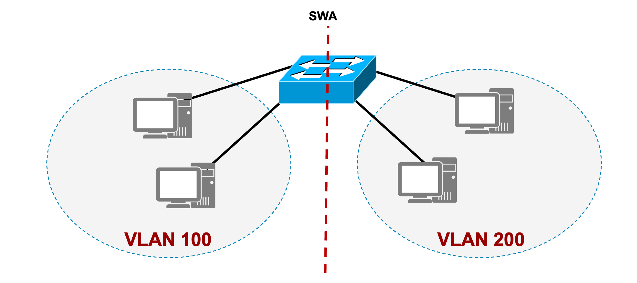
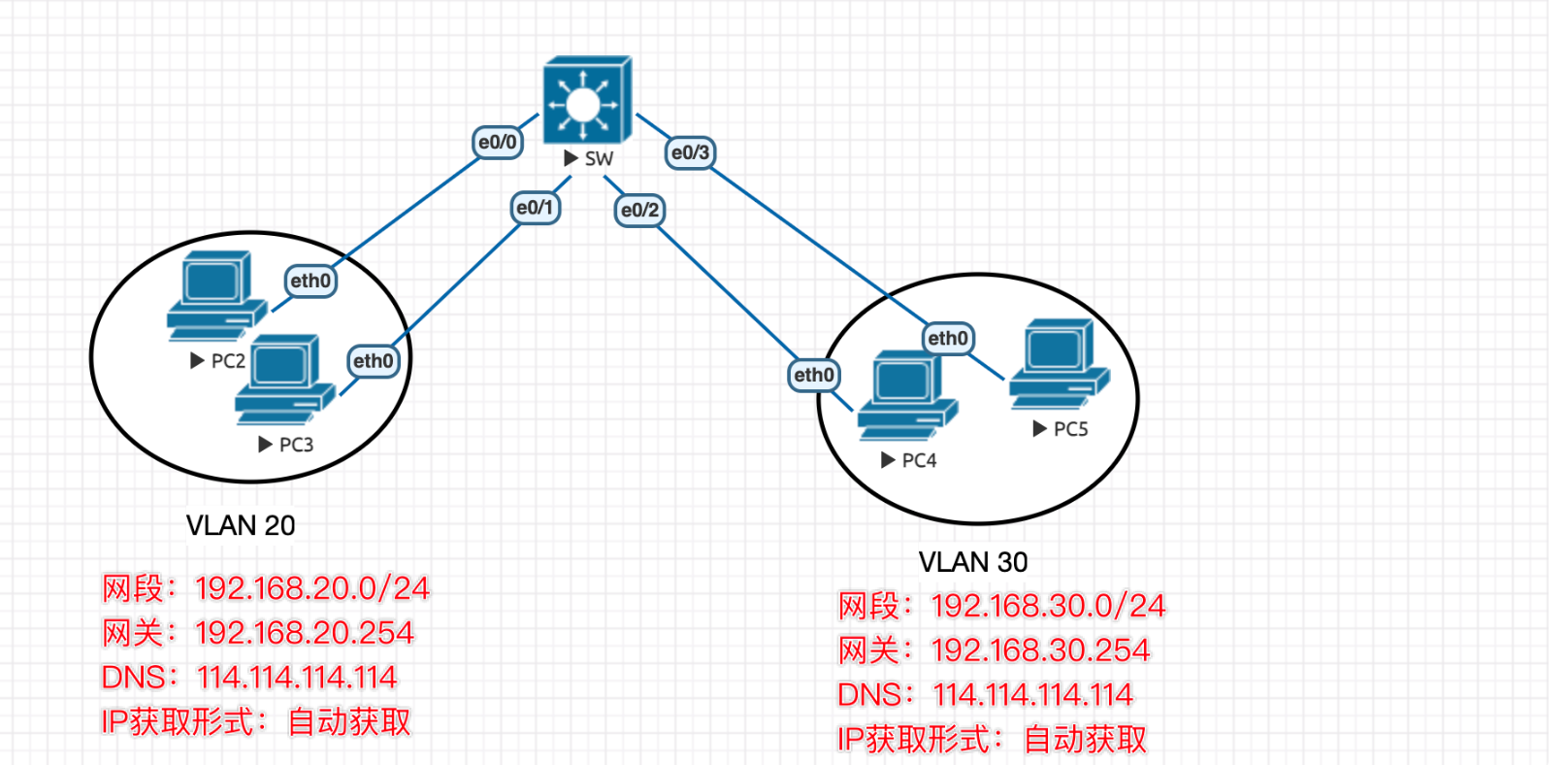
广播域
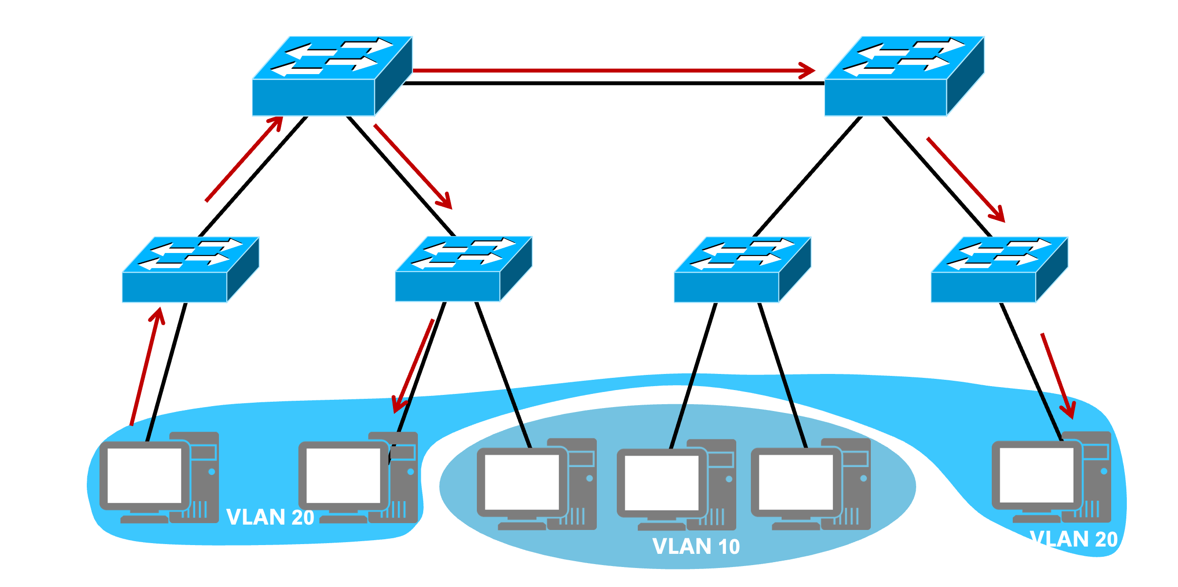
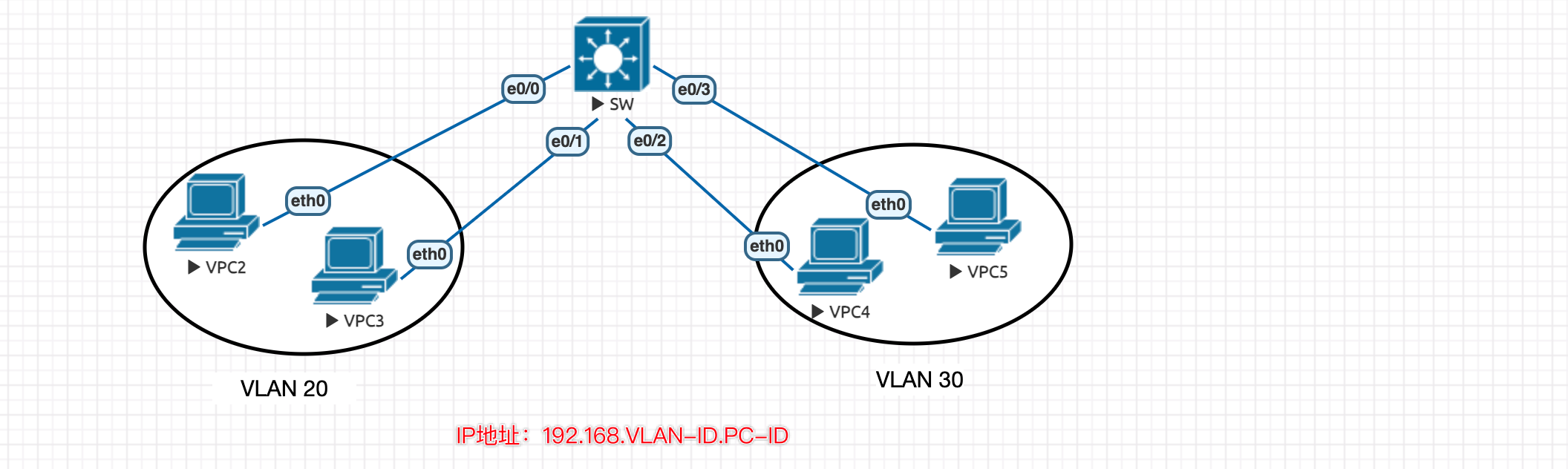
VLAN 技术能隔离广播域。
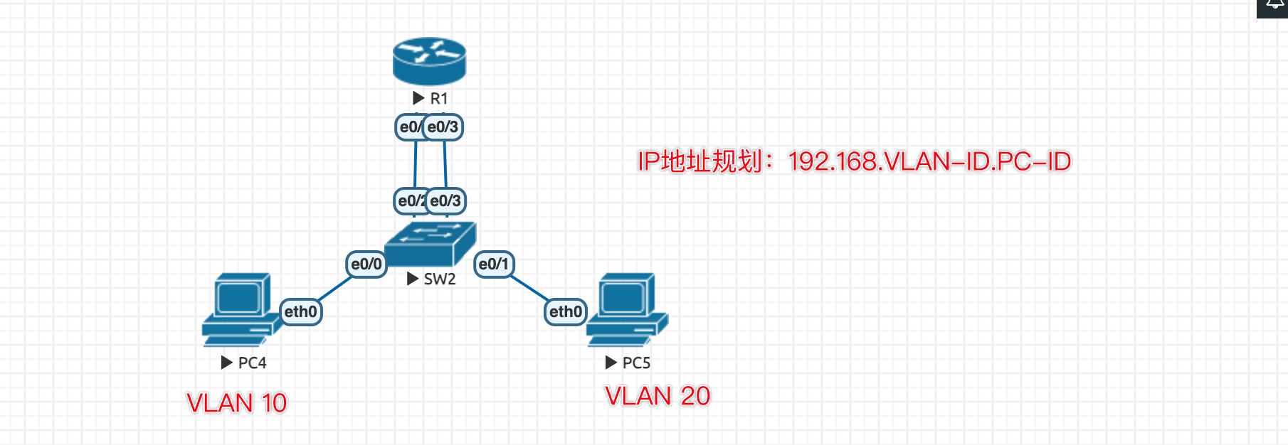
在以上拓扑中,VLAN 20 是一个广播域,而 VLAN 10也是一个广播域。
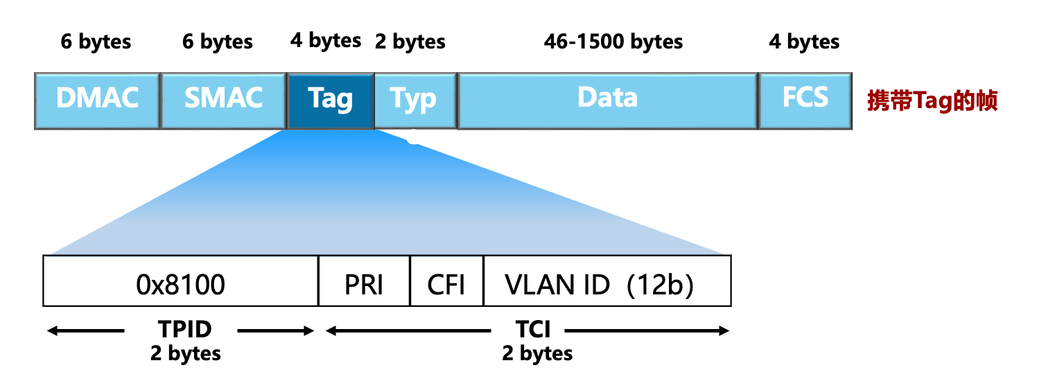
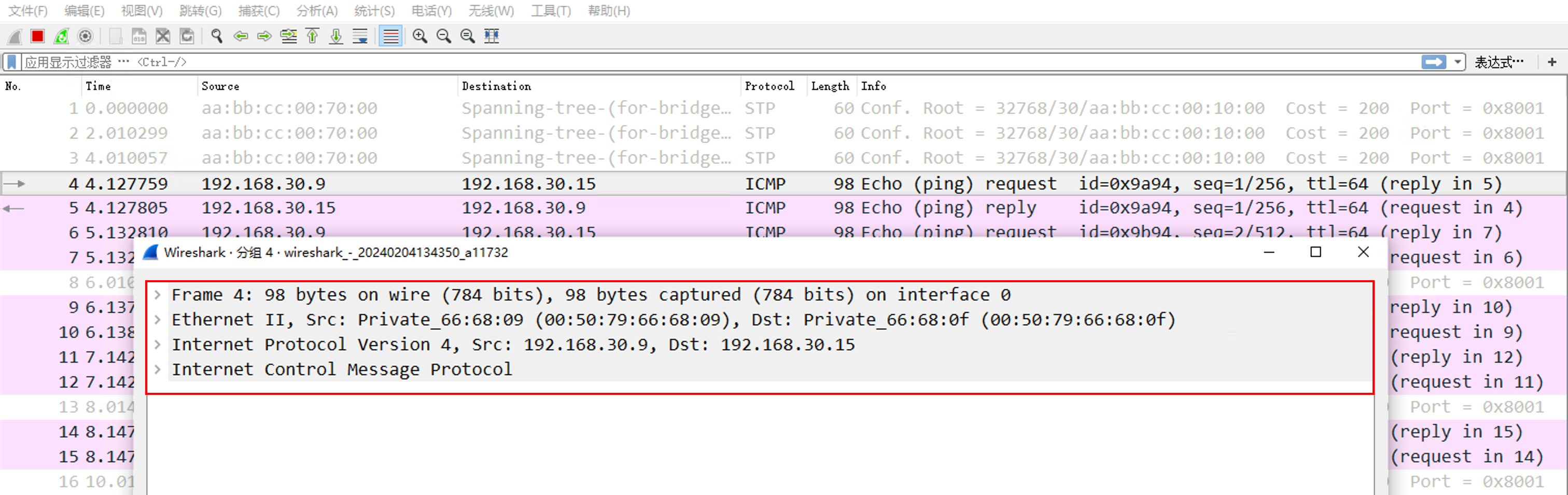
VLAN 帧格式
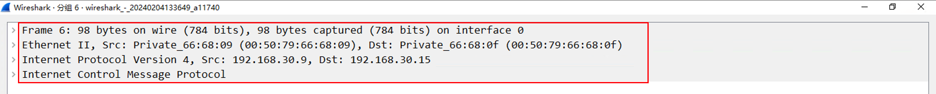
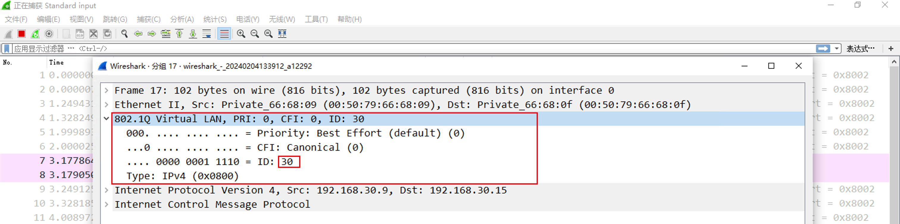
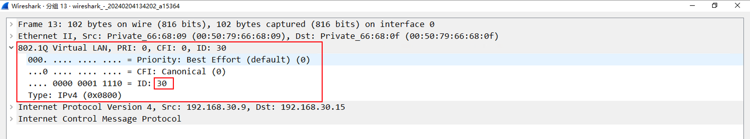
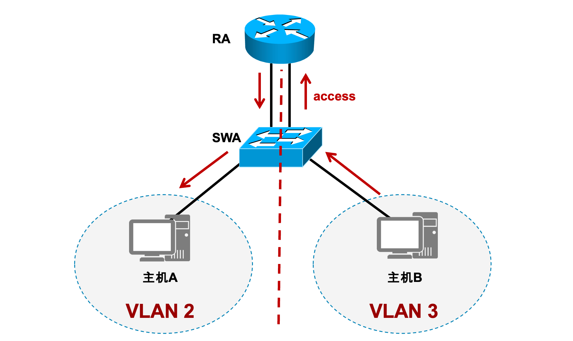
交换机设备通过 Tag 中的 VLAN ID,区分不同VLAN,VLAN 计算机在发送数据的时候,数据本身是没有 Tag 的,而从交换机接口发送出去之后,就带有了 Tag(打标签),但是在交换机与PC连接的接口,在接收数据的时候,会自动的去标签。
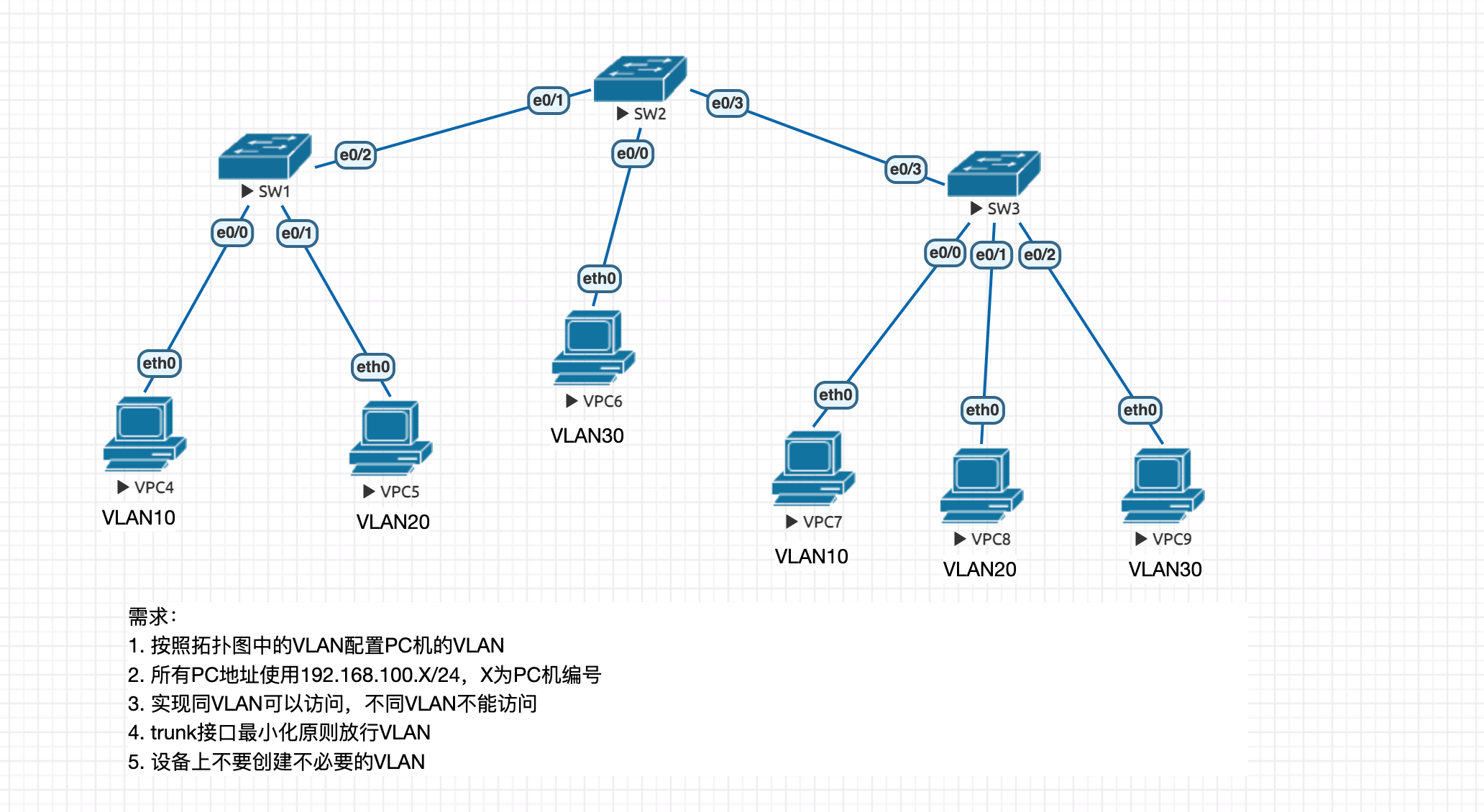
SW1#conf t Enter configuration commands, one per line. End with CNTL/Z. SW1(config)# *Feb 4 15:56:58.372: %SYS-5-CONFIG_I: Configured from console by console SW1(config)#vlan 10,20 SW1(config-vlan)#exit SW1(config)#int e0/0 SW1(config-if)#switchport mode access SW1(config-if)#switchport access vlan 10 SW1(config-if)#int e0/1 SW1(config-if)#switchport mode access SW1(config-if)#switchport access vlan 20
SW2
1 2 3 4 5 6 7 8 9
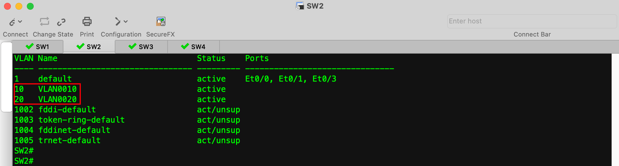
SW2#conf t Enter configuration commands, one per line. End with CNTL/Z. SW2(config)#vlan 10,20,30 SW2(config-vlan)#exit SW2(config)#int e0/0 SW2(config-if)#switchport mode access SW2(config-if)#switchport access vlan 30 SW2(config-if)#exit SW2(config)#
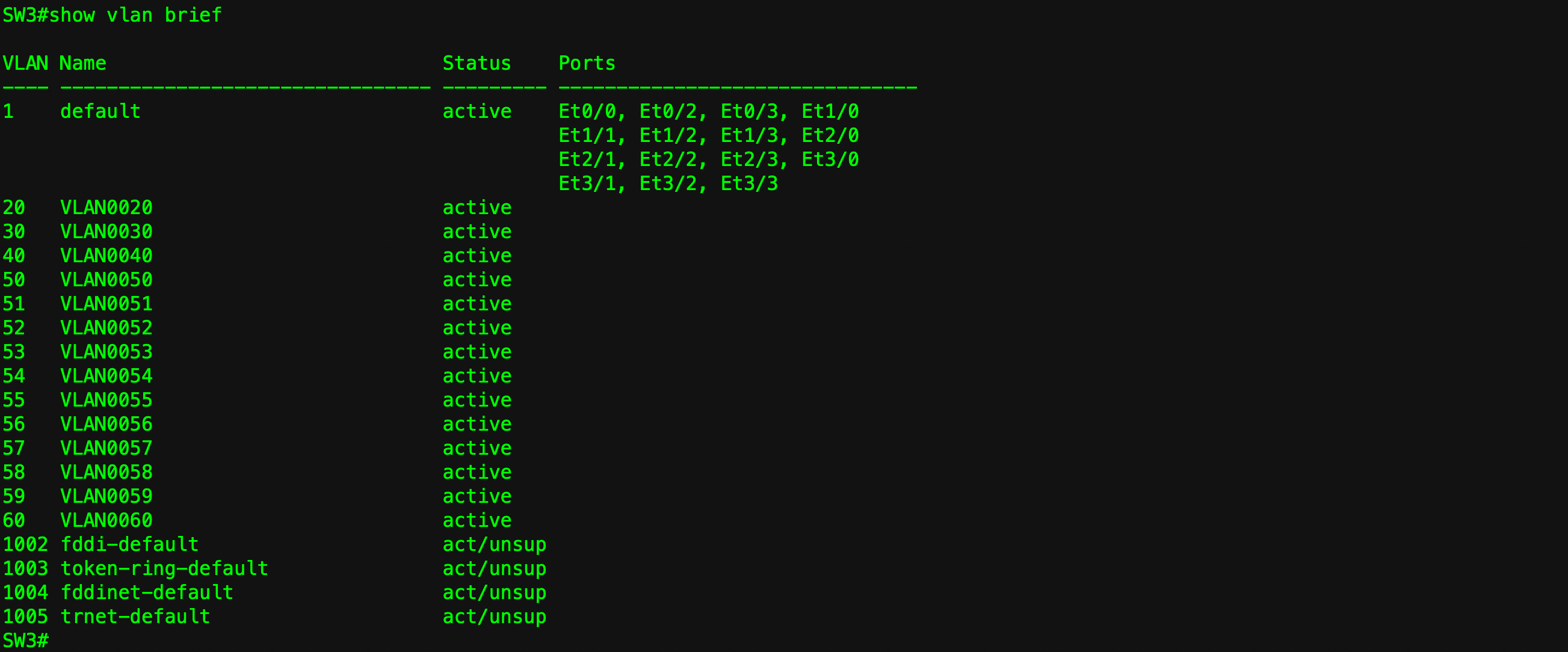
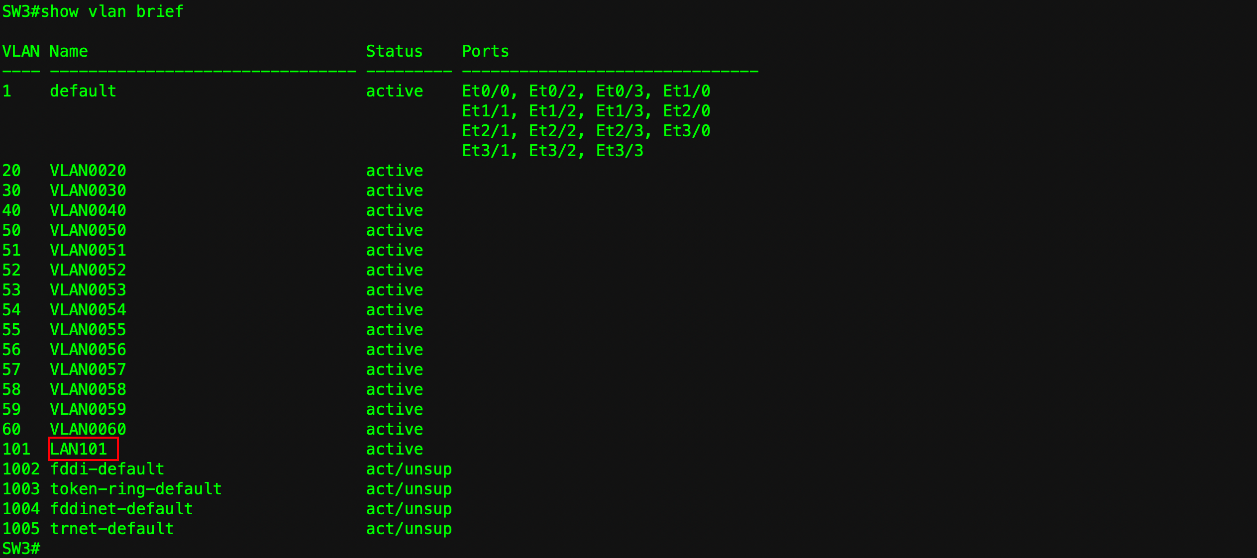
SW3
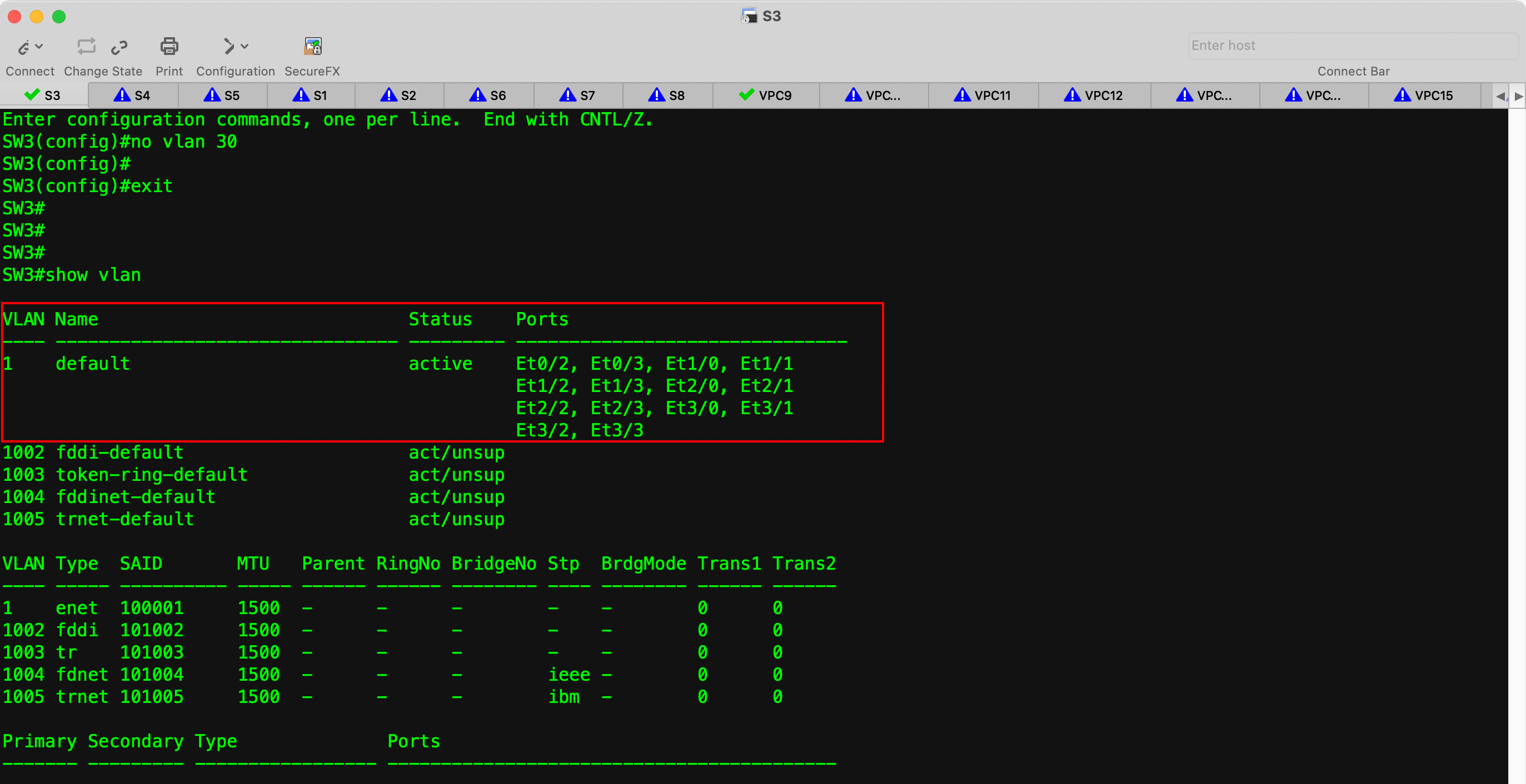
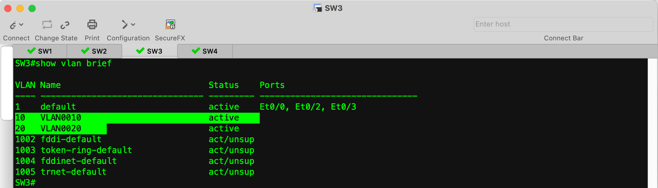
1 2 3 4 5 6 7 8 9 10 11 12 13
SW3# SW3#conf t Enter configuration commands, one per line. End with CNTL/Z. SW3(config)#vlan 10,20,30 SW3(config-vlan)#int e0/0 SW3(config-if)#switchport mode access SW3(config-if)#switchport access vlan 10 SW3(config-if)#int e0/1 SW3(config-if)#switchport mode access SW3(config-if)#switchport access vlan 20 SW3(config-if)#int e0/2 SW3(config-if)#switchport mode access SW3(config-if)#switchport access vlan 30
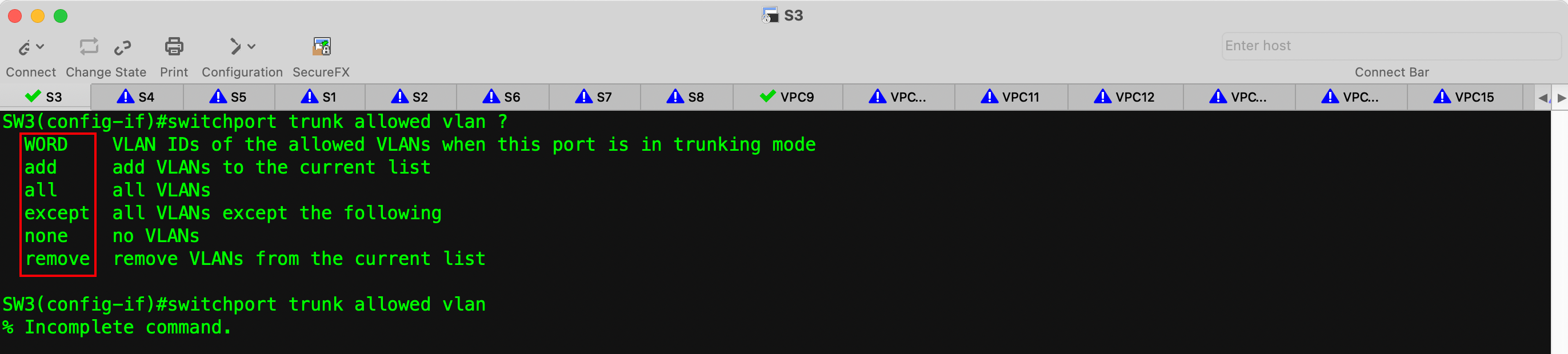
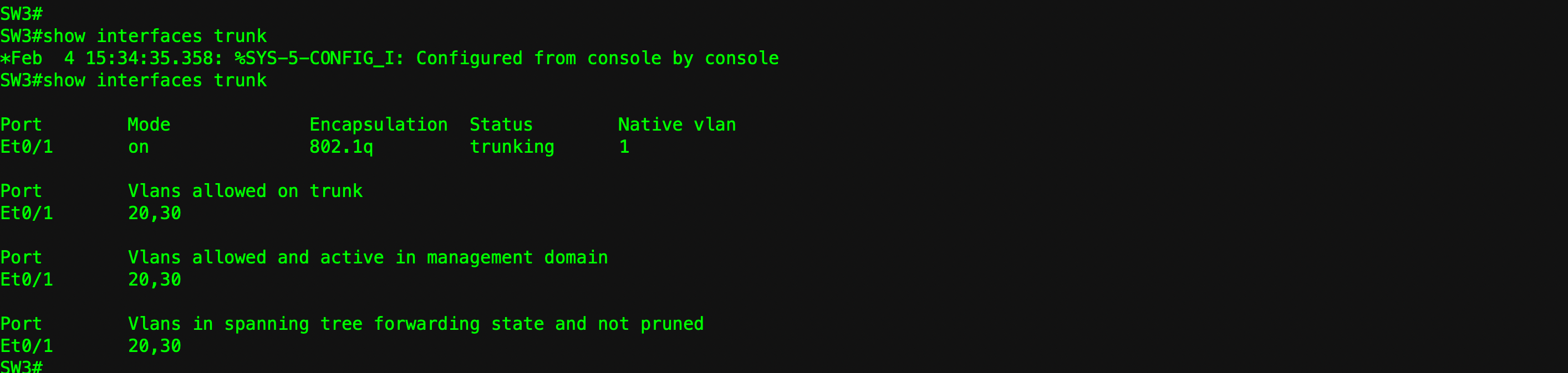
SW3#conf t Enter configuration commands, one per line. End with CNTL/Z. SW3(config)#int e0/3 SW3(config-if)#switchport trunk encapsulation dot1q SW3(config-if)#switchport mode trunk SW3(config-if)#switchport trunk allowed vlan 10,20,30
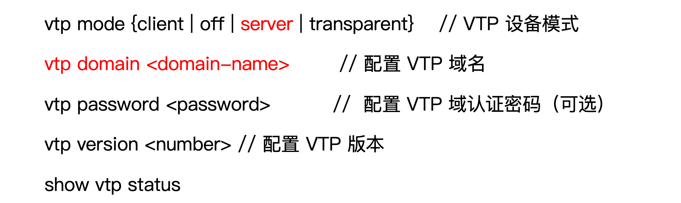
SW1# SW1#conf t Enter configuration commands, one per line. End with CNTL/Z. SW1(config)#vtp mode server Device mode already VTP Server for VLANS. SW1(config)#vtp domain vtp01 Changing VTP domain name from NULL to vtp01
SW2:
1
2
3
4
5
6
SW2#conf t Enter configuration commands, one per line. End with CNTL/Z. SW2(config)#vtp mode client Setting device to VTP Client mode for VLANS. SW2(config)#vtp domain vtp01 Domain name already set to vtp01.
SW3:
1 2 3 4 5 6 7 8 9
SW3#conf t Enter configuration commands, one per line. End with CNTL/Z. SW3(config)#vtp *Feb 5 12:08:23.846: %SYS-5-CONFIG_I: Configured from console by console SW3(config)#vtp mode client Setting device to VTP Client mode for VLANS. SW3(config)#vtp domain vtp01 Domain name already set to vtp01. SW3(config)#
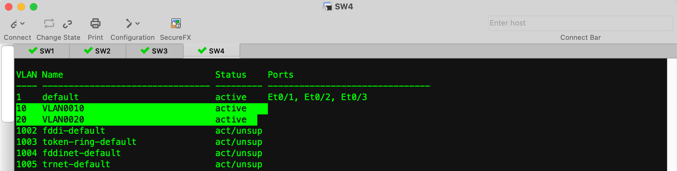
SW4:
1 2 3 4 5 6 7 8 9
SW4# SW4#conf t Enter configuration commands, one per line. End with CNTL/Z. SW4(config)#we *Feb 5 12:08:35.694: %SYS-5-CONFIG_I: Configured from console by console SW4(config)#vtp mode client Setting device to VTP Client mode for VLANS. SW4(config)#vtp domain vtp01 Domain name already set to vtp01.
# 创建 VLAN 并将 PC 加入到相应 VLAN Switch# Switch#conf t Enter configuration commands, one per line. End with CNTL/Z. Switch(config)#vlan 10,20 Switch(config-vlan)#exit Switch(config)#int e0/0 Switch(config-if)#sw ac vlan 10 Switch(config-if)#int e0/1 Switch(config-if)#switchport ac vlan 20
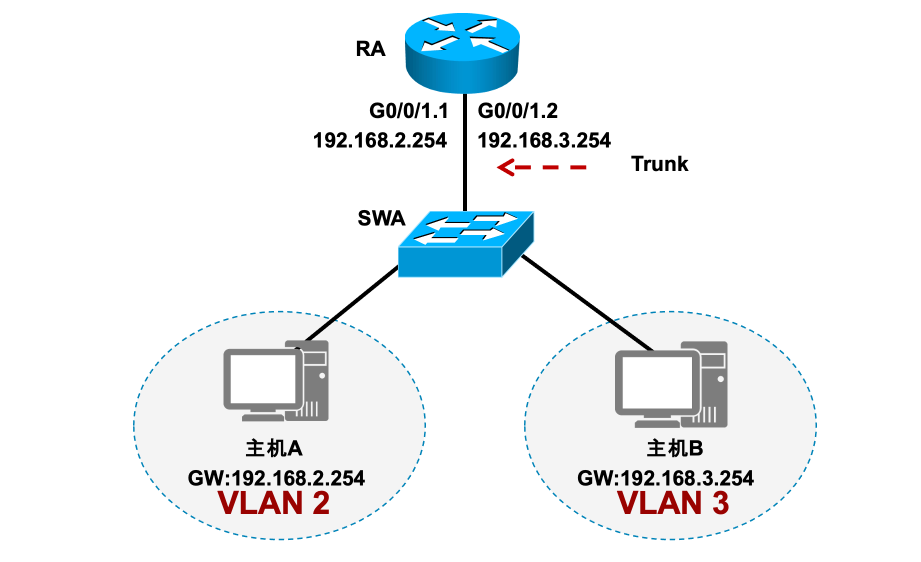
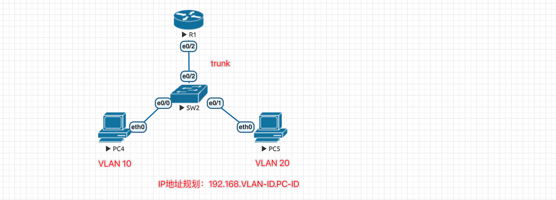
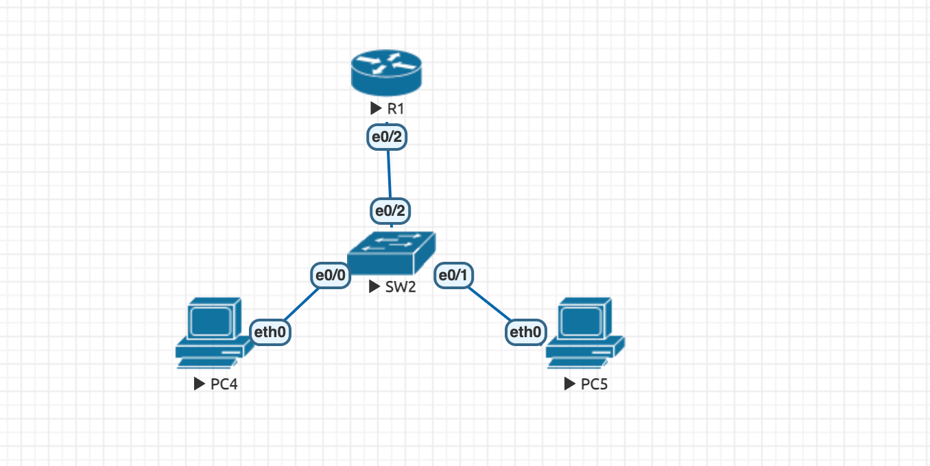
这里可能有个疑问,路由器的接口不是无法接收带有 VLAN ID 的数据包吗,是的,但是路由器的子接口是可以接收带有 VLAN ID 的数据包的,因此可以将该链路设置为 Trunk。
具体实验:
Switch:
1 2 3 4 5 6 7 8 9 10 11 12 13 14
# 将 PC 加入到 相应 VLAN Switch#conf t Enter configuration commands, one per line. End with CNTL/Z. Switch(config)#vlan 10,20 Switch(config-vlan)#exit Switch(config)#int e0/0 Switch(config-if)#switchport access vlan 10 Switch(config-if)#int e0/1 Switch(config-if)#switchport access vlan 20
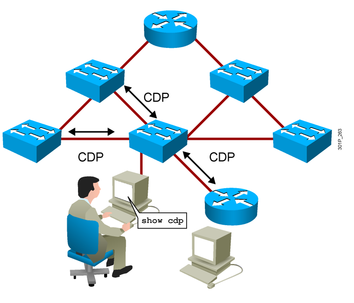
Switch#show cdp
Global CDP information:
        Sending CDP packets every 60 seconds
        Sending a holdtime value of 180 seconds
        Sending CDPv2 advertisements is enabled
Switch#show cdp neighbors
Capability Codes: R - Router, T - Trans Bridge, B - Source Route Bridge
                  S - Switch, H - Host, I - IGMP, r - Repeater, P - Phone,
                  D - Remote, C - CVTA, M - Two-port Mac Relay

Device ID        Local Intrfce     Holdtme    Capability  Platform  Port ID
Router           Eth 0/2           154              R B   Linux Uni Eth 0/2


 微信
微信 支付宝
支付宝